
Precision CNC components for robotics
CNC Machined Precision Spacers and Components for Robotics Applications
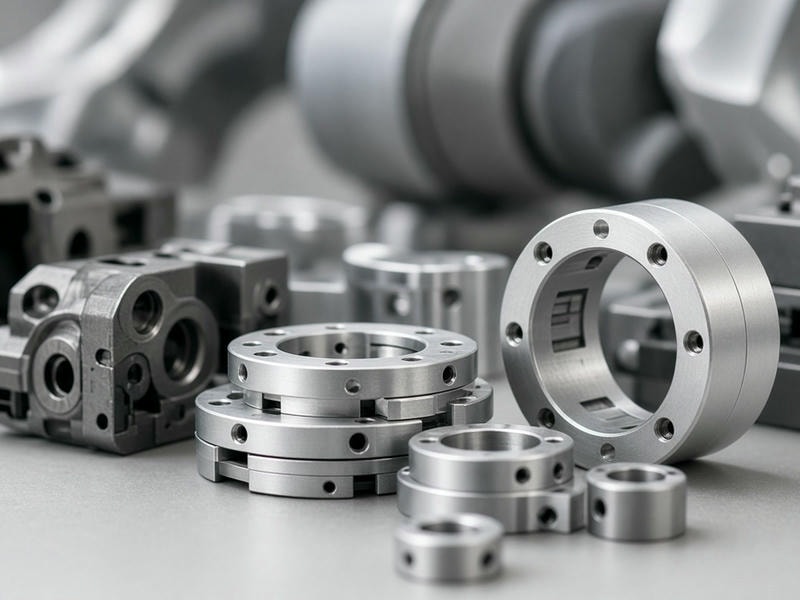
Robotic assemblies require tight dimensional control, minimal weight, and high repeatability across joints, drives, and structural frames. SpacerMFG manufactures custom precision spacers, sleeves, standoffs, bushings, and turned shafts directly to your print.
Exact bore tolerances, length dimensions, and chamfer specifications help engineering teams eliminate assembly shimming, reduce rotational mass, and maintain axis alignment in robotic systems.
±0.01 mm
Face parallelism available for demanding bearing and gear interfaces
1.5 mm
Minimum turning bore capability for compact assemblies
Engineering challenges
Built around the demands of robotic motion
Industrial arms, autonomous mobile robots, and collaborative robots need more than standard catalog hardware. Custom geometry and controlled tolerances help protect alignment, efficiency, and service life.
Prevent tolerance stack-up
Spacers between bearings and housings can require face parallelism within ±0.01 mm to prevent offset loads on planetary or harmonic gear sets.
Reduce moving mass
7075-T6 aluminum spacers provide a strong strength-to-weight ratio, helping reduce motor torque requirements and dynamic inertia.
Control seating and clearance
Controlled ID and OD tolerances support reliable press fits or running clearances on hardened shafts and bearing interfaces.
Protect internal harnesses
Smooth internal bores and deburred chamfers help prevent cable abrasion during continuous articulation through hollow joints.
Manufacturing capabilities
Machined to your drawing, from prototype to production
We use multi-axis CNC turning and milling centers and work directly from STEP, IGES, DXF, or PDF engineering prints. Production can scale from a single prototype to high-volume requirements.
| Parameter | CNC turning capabilities | CNC milling capabilities |
|---|---|---|
| Typical components | Spacers, sleeves, standoffs, bushings, pins, shafts | Mounting brackets, sensor plates, gear housings, EOAT blocks |
| Outer diameter / size range | 2 mm to 300 mm | Up to 500 mm × 400 mm × 300 mm |
| Bore / inner diameter | Down to 1.5 mm | Custom pocket and hole patterns |
| Standard tolerances | ±0.01 mm to ±0.05 mm, as specified | ±0.02 mm to ±0.05 mm, as specified |
| Machined features | Internal/external threads, snap-ring grooves, steps, chamfers | Counterbores, thread tapping, keyways, complex profiles |
| Surface finish | Ra 0.8 µm to Ra 3.2 µm standard; ground to Ra 0.4 µm | Ra 1.6 µm to Ra 3.2 µm standard |
Material selection
Materials matched to load, weight, and environment
Certified raw materials are selected to match structural, electrical, wear, and environmental requirements.
Aluminum alloys
6061-T6, 7075-T6, and 2024 for structural spacers, frame mounts, and EOAT fixtures where low weight is critical.
Stainless steel
304, 316L, and 17-4 PH for corrosion-resistant environments, cleanroom robots, and high-load joint assemblies.
Carbon and alloy steels
1215, 4140, and 1045 for drive shafts, wear bushings, and high-stress sleeves requiring heat treatment.
Brass and copper alloys
C36000 and phosphor bronze for low-friction bushings, grounding standoffs, and anti-galling thrust washers.
Engineering plastics
POM/Delrin, PEEK, PTFE, and Nylon for electrical isolation, ultra-low weight, or low wear without lubrication.
Finishing and quality
Ready-to-assemble components for demanding motion systems
Finishing processes are managed in-house or through certified processing partners to support friction, wear, corrosion, and cleanroom requirements.
Anodizing
Type II clear or color and Type III hardcoat, including MIL-A-8625 Type III wear protection.
Electroless nickel plating
Uniform coating over complex internal bores and threads on steel and copper components.
Passivation
Removes free iron from stainless steel for cleanroom, medical, and semiconductor robotics.
Precision grinding
Outer diameter and face flatnesses down to ±0.005 mm for bearing sleeves and pivot pins.
Deburring and edge conditioning
Mechanical or ultrasonic deburring removes sharp edges, protects wiring, and prevents chip shedding inside sealed drive enclosures.
Application coverage
One precision parts partner across the robotic system
Articulated arms and cobots
Stepped face spacers maintain axial spacing between thin-section bearings and wave generators. Concentric steps machined into one spacer reduce component count and assembly alignment errors.
- • Bearing preload washers
- • Lightweight joint housings
- • Stepped joint spacers
AMR and AGV drive systems
Heavy-duty steel sleeves handle radial impacts in drive wheels and suspension linkages. Controlled length tolerances keep shafts aligned with motors without binding.
- • Heavy-wall axle sleeves
- • Wheel hub spacers
- • Motor mount standoffs
EOAT and control systems
Lightweight hollow standoffs allow air lines and signal cables to pass through structural mounting points while preserving payload capacity.
- • Gripper finger pivot bushings
- • Quick-change adapter sleeves
- • Sensor and PCB mounting collars
Production workflow
From drawing to traceable delivery
A structured process keeps engineering, procurement, inspection, and delivery milestones visible.
- 1
Drawing review and DFM assessment
Review STEP, IGES, or PDF files for dimensions, tolerances, threads, and material callouts.
- 2
Quotation and material sourcing
Receive itemized pricing, setup fees where applicable, lead times, shipping options, and verified material test reports.
- 3
CNC machining and in-process inspection
Setup-verified equipment and first-piece inspection confirm critical dimensions before the production run continues.
- 4
Secondary finishing and QA
Parts are deburred, treated, and checked with optical comparators, thread gauges, micrometers, or CMM equipment.
- 5
Traceable packaging and delivery
Cleaned parts are packed to prevent transit damage, with individually wrapped finishes and inspection reports available upon request.
Request a quote
Get an actionable engineering quote for custom robotics hardware
Whether you are developing a robotic prototype or scaling repeat assembly production, send your part specifications for technical feedback, pricing, and estimated lead times within 24 hours.
What to include in your RFQ
- 2D or 3D drawings: PDF files with tolerance callouts, or STEP/IGES files.
- Material and finish: For example, 6061-T6 with black Type II anodizing.
- Order quantity: Prototype volumes of 1–10 pieces, pilot runs of 100–500 pieces, or scheduled production quantities.
Contact our sourcing and engineering team
Share your drawings and requirements through the inquiry form to start a technical review.
Email: info@spacermfg.com
Facility address: