
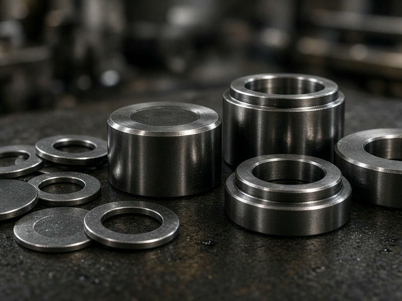
Precision-machined transmission components
Custom Gearbox Spacers Precision Machined to Your Print
In power transmission systems, gearboxes, and speed reducers, proper gear meshing, shaft positioning, and bearing preload rely on accurate spacer dimensions. A deviation of just a few microns in thickness or parallelism can lead to improper gear tooth engagement, excessive backlash, heat generation, or early bearing failure.
SpacerMFG manufactures custom precision gearbox spacers, sleeves, and thrust washers directly from customer prints. Based in Shenzhen, China, we support equipment OEMs, industrial automation builders, and gearbox rebuilder operations with turned and ground spacers designed to withstand high torque and continuous axial loads.
±0.005 mm
Thickness tolerance capability
Ra 0.4 µm
Ground thrust-face finish
Manufacturing capabilities
Dimensional control for demanding gearbox applications
Gearbox applications demand strict control over face parallelism, bore-to-OD concentricity, and surface finish. We combine multi-axis CNC turning, milling, and surface grinding to produce spacers that meet tight engineering tolerances.
| Parameter | Manufacturing Capability |
|---|---|
| Component Types | Bearing preload spacers, shaft positioning sleeves, stepped spacers, flanged spacers, thrust washers |
| Material Options | Alloy steel (4140, 8620), carbon steel (1045), stainless steel (304, 316, 17-4PH), aluminum (6061-T6, 7075-T6), brass and bronze |
| Dimensional Range | Custom outer diameters, inner diameters, and lengths from micro-components to large heavy-machinery sizes |
| Thickness Tolerance | Down to ±0.005 mm (±0.0002 in), depending on material and geometry |
| Parallelism & Flatness | Controlled to within 0.005 mm via precision grinding where required |
| Surface Finish | Standard turned finish up to Ra 0.4 µm (16 µin) for ground thrust faces |
| Secondary Operations | Heat treatment, hardening, carburizing, precision grinding, deburring, black oxide, passivation, and anodizing |
| Production Volume | Rapid prototypes, low-volume pilot batches, and repeat OEM production runs |
Component configurations
Gearbox spacer designs built around your assembly
Every gearbox design has unique mounting constraints and load conditions. We machine custom spacers to match your exact CAD files and specifications.
Bearing Preload & Setting Spacers
Positioned between tapered roller bearings or angular contact ball bearings, these spacers establish precise endplay or preload settings. We control thickness and face parallelism to ensure uniform loading across the bearing races.
Gear & Pinion Shaft Positioning Sleeves
Mounted directly over input or output shafts, shaft sleeves retain gears, sprockets, and bearings against shaft shoulders. We maintain tight ID tolerances for slip fits or press fits without shaft distortion.
Stepped & Flanged Gearbox Spacers
Designed with multiple diameters or integrated retaining flanges to locate internal components within housing bores. These profiles eliminate the need for multi-piece assembly stacks, simplifying assembly lines.
High-Wear Thrust Spacers & Washers
Machined from bronze, brass, or hardened steel, these low-friction spacers manage sliding axial loads between rotating gears and stationary housing walls.
Material selection
Match the material to the load and environment
Selecting the right material depends on operating torque, rotational speed, thermal expansion, and environmental exposure.
Alloy Steel (4140, 8620, 4340)
Preferred for heavy-duty industrial gearboxes subject to severe impact and high axial loads. Case-hardened or through-hardened options provide excellent fatigue resistance.
Carbon Steel (1045, 1018)
A cost-effective option for standard industrial speed reducers where extreme surface hardness is not required. Often finished with black oxide or zinc plating.
Stainless Steel (304, 316, 17-4PH)
Used in food processing equipment, marine drives, and chemical agitator gearboxes requiring corrosion resistance and washdown capability.
Bronze & Brass Alloys (C93200 / SAE 660, C36000)
Used for sliding contact zones where self-lubrication or anti-galling behavior against steel shafts is necessary.
Aluminum Alloys (6061-T6, 7075-T6)
Ideal for lightweight robotics actuators, aerospace gear sets, and automotive racing transmissions where mass reduction is critical.
Machining and finishing
Finishing steps for reliable continuous-cycle performance
To achieve structural integrity and long operating life under continuous cycle loads, we run dedicated precision finishing steps.
Precision CNC Turning
Ensures tight concentricity between the inner bore and outer diameter, keeping the spacer balanced at high shaft speeds.
Double-Disc & Surface Grinding
Removes tool marks and establishes flat, parallel faces to prevent localized point-loading on bearing rings and shaft misalignments.
Edge Deburring & Radius Polishing
Internal and external edges are deburred to prevent stress risers, burr detaching inside the oil bath, or seal tearing during assembly.
Surface Coatings
Protective finishes include black oxide, zinc plating, nickel plating, anodizing, and passivation according to drawing notes.
Quality inspection
Batch verification before dispatch
Every batch of gearbox spacers undergoes dimensional verification before dispatch, with inspection focused on the features that influence fit, preload, alignment, and lubrication-system cleanliness.
-
1
Incoming Material Inspection
Raw stock is verified for material composition and grade compliance.
-
2
In-Process Checks
Critical features such as bore sizes, snap-ring grooves, and step heights are checked during CNC production.
-
3
Final Quality Control
Thickness, flatness, and parallelism are verified using micrometers, height gauges, and CMM equipment.
-
4
Deburring & Cleanliness Verification
Spacers are washed to remove metal chips, oils, and abrasive residue that could contaminate gearbox lubrication systems.
Request a quote
Send your gearbox spacer requirements
We manufacture gearbox spacers to custom engineering prints. Whether you need 10 prototype pieces for testing or 10,000 repeat production units, our engineering team is ready to review your files.
What to Include in Your RFQ
- 012D Drawing (PDF) and 3D CAD File (STEP, IGES, or X_T)
- 02Material specification and required heat treatment or hardness, if applicable
- 03Critical tolerances, including thickness, parallelism, and bore tolerance
- 04Required surface finish and plating or coating
- 05Order quantity, prototype quantity, and annual volume forecast
Discuss your drawing
Share your requirements with our engineering team for a practical production review.