
Custom PCB Spacers Made to Your Print
SpacerMFG manufactures precision PCB spacers, standoffs, and distance sleeves directly from CAD files and technical drawings. From Shenzhen, our CNC turning and milling facility supports prototypes within days and high-volume OEM production.
±0.01 mm
Length tolerance available
M1–M12
Metric thread range
500,000+
Repeat production volume
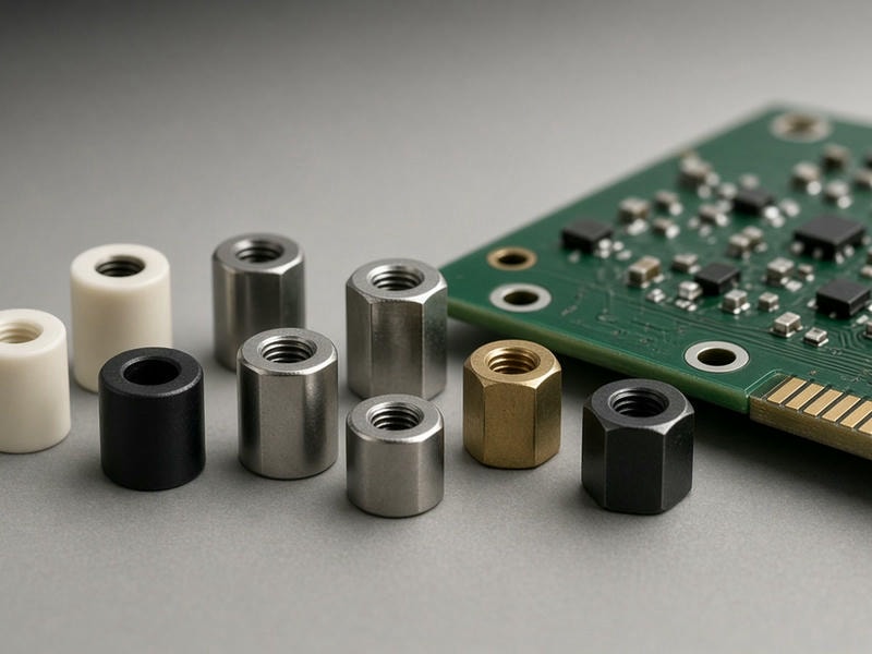
Direct-to-drawing production
Machined dimensions, threads, profiles, and finishes are controlled to your specification.
Built for reliable assembly
Precise spacing protects the entire electronic assembly
PCB spacers maintain physical clearance, manage thermal paths, absorb vibration, and prevent unwanted contact between circuit boards and conductive enclosure walls. When standard catalog hardware does not match your design, every dimension can be machined to specification.
Prevent board distortion
Consistent spacer lengths reduce mechanical stress across solder joints and surface-mount components, helping prevent micro-cracks over time.
Secure thread engagement
Custom thread depth, pitch, and configuration help prevent strip-out during manual or automated torque-down operations.
Maintain enclosure alignment
Controlled ID, OD, length, and flange dimensions protect SMD clearance zones and keep multi-tier board stacks accurately aligned.
Manufacturing capabilities
Configured for small precision components
High-precision CNC lathes, Swiss automatic turning centers, and multi-axis milling machines support intricate electronic hardware and small-diameter turned components.
| Parameter | Specification / Range | Notes |
|---|---|---|
| Outer Diameter | 1.5 mm to 80 mm | Custom hex, round, or knurled profiles |
| Inner Diameter | From 0.8 mm up to custom requirements | Smooth bore, clearance holes, or tapped |
| Length Tolerance | Standard ±0.05 mm; up to ±0.01 mm on request | Controls board stack-up variance |
| Diameter Tolerance | Standard ±0.02 mm; up to ±0.005 mm on request | For tight clearance zones |
| Thread Configurations | M1 to M12; UNC/UNF #0-80 to 1/2" | Male-female, female-female, male-male, or unthreaded |
| Thread Accuracy | 6H / 6g internal and external classes | Verified with thread plug and ring gauges |
| Surface Finish | Ra 0.8 µm to Ra 3.2 µm standard | Polished or bead-blasted options available |
| Production Volumes | 100 prototype pieces to 500,000+ repeat OEM pieces | Fast-turn prototyping available |
Material selection
Match the spacer to its operating environment
Material choice balances structural strength, weight, thermal performance, electrical behavior, corrosion resistance, and cost.
Aluminum
6061-T6, 7075-T6, and 2024 offer low weight, easy machining, and strong thermal dissipation. Anodizing supports color coding or electrical isolation.
Stainless Steel
303, 304, and 316 provide strength and corrosion resistance for medical, marine, food processing, and harsh industrial environments.
Brass
C36000 free-cutting brass combines machinability, electrical conductivity, and spark resistance for RF shielding and telecommunications.
Steel
12L14, 1018, and alloy steels provide cost-effective structural strength for heavy industrial machinery logic panels.
Engineering plastics
PEEK, Delrin / POM, Nylon, and PTFE deliver electrical isolation, low weight, and chemical resistance where metal spacers are unsuitable.
From design to assembly
Reduce lead times with direct-to-drawing machining
Direct production removes the need to trim standard spacers, re-tap threads, or combine washers and lock rings. Components arrive ready for your assembly line.
Step 01
Your CAD or drawing
Share dimensions, tolerances, materials, finishes, and expected quantities.
Step 02
Direct CNC quote
Our engineering team reviews manufacturability and prepares a comprehensive quotation.
Step 03
Precision machining
Turning, milling, threading, deburring, cleaning, and finishing are managed to specification.
Step 04
Ready for assembly
Consistent parts reduce rework, stacking workarounds, and thread strip-outs.
Controlled stack-up
Uniform lengths preserve connector mating depth and panel alignment.
Integrated features
Step shoulders, retention grooves, pilot shanks, and knurling can be machined into one part.
Less in-house modification
Drop-in components save labor and reduce prototype scrap.
Configuration guide
Choose the geometry for your board layout
Threaded or unthreaded
- Female-female: Secures two circuit boards with screws from both ends.
- Male-female: Stacks multiple PCBs or mounts a board to a threaded chassis boss.
- Clearance sleeves: Uses long pass-through bolts or rivets for an economical option.
Hex or round profile
- Hex spacers: Provide wrench or automated socket engagement for controlled torque.
- Round spacers: Reduce the footprint where SMD density and clearance are restricted.
Isolation or grounding
- Grounding: Brass or aluminum can establish a low-resistance path to a metal housing.
- Isolation: Delrin, PEEK, or hard-anodized aluminum helps prevent arcing and ground loops.
Available secondary processing
Type II and Type III hardcoat anodizing, passivation, zinc/nickel/tin/gold electroplating, polishing, bead blasting, and laser marking for part numbers, batch codes, or polarity identification.
Quality assurance
Verification at every production stage
Minor thread errors or burrs can damage multi-layer PCBs and cause field failures. Our quality gates are designed to protect fit, finish, and assembly reliability.
- 1
First-piece inspection
Dimensions are verified against engineering drawings before full production begins.
- 2
In-process thread gauging
Internal and external threads are checked with calibrated GO/NO-GO plug and ring gauges to Class 6H/6g.
- 3
Optical and micro-caliper measurement
Length, wall thickness, chamfer angles, and burr-sensitive features are measured precisely.
- 4
Cleaning and surface checks
Parts are deburred and ultrasonically cleaned to remove filings and grease from sensitive assemblies.
- 5
Material traceability
Mill test reports and certificates of compliance are available upon request.
Request a quote
Send your PCB spacer requirements to our engineering team
Submit your design files for manufacturability review and receive a comprehensive quotation within 24 hours.
Include these details in your RFQ
- CAD files in STEP, IGES, or DXF, plus a dimensioned PDF
- Material grade, such as Aluminum 6061-T6, Brass C360, Stainless 303, or Delrin
- Thread size, pitch, and internal or external thread lengths
- Surface finish, plating, anodizing, passivation, or raw-machined requirements
- Prototype quantity and anticipated annual production volume
Contact SpacerMFG
Our team can review your drawing, recommend a suitable configuration, and prepare a production plan.