
Precision CNC components manufactured to print
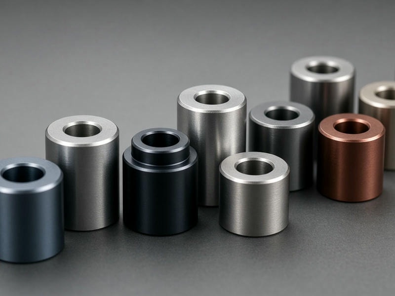
Custom Precision Mounting Spacers Manufactured to Print
SpacerMFG manufactures custom mounting spacers, standoffs, sleeves, and bushings directly from customer drawings. We support machinery OEMs, robotics developers, industrial automation integrators, and electronics manufacturers with components built to exact dimensions, materials, and finishing specifications.
Submit 2D drawings and 3D CAD files to receive lead-time options within 24 hours.
±0.005 mm
Tolerance available to drawing specification
1–50,000+
Prototype through repeat production quantities
Mechanical function
Dimensional control for reliable assemblies
Mounting spacers establish precise clearance, maintain alignment between stacked plates, isolate electrical components, and distribute clamping loads across mating fasteners.
Bore alignment and clearance
Custom inner diameters prevent bolt binding while controlled concentricity limits shaft deflection and lateral play.
Parallelism and seating
Precision-faced ends keep circuit boards, sensors, and brackets flat without stress concentrations or bowing under torque.
Load-bearing capacity
Solid turned metal spacers support heavy axial loads where plastic or stamped sheet metal alternatives may compress.
Thermal and electrical management
Aluminum transfers heat across enclosures, while stainless steel resists aggressive washdowns and chemicals.
Manufacturing capabilities
CNC production for simple and complex spacer geometries
Dedicated CNC turning centers, multi-axis lathes, and CNC milling machines produce components from simple round sleeves to stepped, flanged, square, hexagonal, and threaded configurations.
| Parameter | Machining capability | Engineering notes |
|---|---|---|
| Outer diameter (OD) | 2.0 mm to 300.0 mm | Turned, ground, or milled exterior profiles |
| Inner diameter (ID) | Down to 1.0 mm | Straight bores, stepped bores, or counterbores |
| Length / height | 1.5 mm to 500.0 mm | Face-ground for tight parallel seating |
| Standard tolerances | ±0.02 mm standard | Down to ±0.005 mm upon drawing specification |
| Bore concentricity | ≤ 0.015 mm | Machined in a single setup for high coaxiality |
| Internal / external threads | M2 to M30, UNC/UNF | Cut or tapped to class 2B/6H standards |
| Surface finish | Ra 0.8 µm to Ra 1.6 µm | Grinding available down to Ra 0.2 µm |
| Batch volumes | 1 to 50,000+ pieces | Prototypes, pilot runs, and repeat production |
Straight round
Plain cylindrical sleeves with tight ID/OD concentricity.
Stepped & shoulder
Dual-diameter profiles for axial location and standoff height.
Flanged
Integrated flanges distribute load and provide end-stop alignment.
Threaded
Male, female, and male-female combinations in round or hex stock.
Square & hexagonal
Flat outer surfaces simplify wrench tightening during assembly.
Material engineering
Select the right material and finish
Material selection impacts weight, corrosion resistance, tensile strength, electrical conductivity, and service life. Certified raw materials and full traceability are available upon request.
| Material | Grades | Best applied for | Key traits |
|---|---|---|---|
| Aluminum | 6061-T6, 7075-T6, 2024 | Robotics, aerospace, electronics enclosures | Lightweight, strong, thermally conductive |
| Stainless steel | 304, 316L, 303, 17-4 PH | Medical, food processing, marine hardware | Corrosion resistant, chemically stable, strong |
| Carbon & alloy steel | 12L14, 1045, 4140 | Machinery, automotive, fixtures | Wear resistant and cost-effective |
| Brass & bronze | C36000, C93200 | Grounding, bushings, fluid systems | Non-sparking, conductive, low-friction options |
| Engineering plastics | POM, PEEK, PTFE | Electrical and low-friction isolation | Dielectric, chemically resistant, non-galling |
Secondary operations and surface finishing
Anodizing
Type II or Type III hardcoat protects aluminum; clear, black, and color finishes are available. Hardcoat adds surface hardness up to 60 HRC.
Passivation
Stainless steel passivation removes free iron to maximize corrosion resistance in accordance with ASTM A967.
Nickel and zinc plating
Corrosion barriers protect carbon steel spacers in high-moisture environments.
Black oxide
A non-reflective finish with mild corrosion resistance and minimal dimensional impact.
Deburring and radiusing
Vibratory tumbling and hand deburring eliminate sharp edges for safe handling and flat seating.
Laser marking
Part numbers, lot codes, and identification marks can be etched onto spacer exteriors.
Configuration guidance
Match process and geometry to the application
Choosing the appropriate process and configuration helps control unit cost while maintaining structural reliability.
Does the application require threads?
Yes
Threaded spacers / standoffs
Male-female or female-female configurations can replace separate nuts and washers.
No
Plain or stepped spacers
Turned clearance bores work with standard pass-through bolts.
Application-specific solutions
Industrial automation and robotics
Lightweight 6061-T6 aluminum spacers reduce end-of-arm tooling inertia while maintaining encoder and motor mount spacing.
Machinery OEMs
High-strength steel sleeves ground to ±0.005 mm length tolerances provide uniform clamping force across heavy cast housings.
Electronics and instrument enclosures
Threaded brass or aluminum standoffs support multi-layer PCB stacking and prevent short circuits and board flex under vibration.
Automotive and mobility systems
Mass-produced turned stainless steel spacers provide wear-resistant mounting for sensors, fluid lines, and chassis brackets.
Quality assurance
Inspection and delivery aligned to your schedule
Every batch is inspected for drawing compliance before dispatch using calibrated optical comparators, micrometers, thread plug gauges, and Coordinate Measuring Machines.
Production lead-times
Rapid prototyping, 1–50 pieces: Ships in as fast as 3 to 5 business days for physical fit-up testing.
Low-to-medium production, 50–2,000 pieces: Typical lead time of 7 to 10 business days.
High-volume repeat production, 2,000+ pieces: Scheduled releases, blanket purchase orders, and stock-holding agreements are available.
Request a quote
Send your drawings to our engineering team
We review geometries, tolerances, material callouts, and finishing requirements to provide factory-direct pricing and lead-time options.
What to include in your RFQ
- 1. Drawing files: 2D PDF with tolerances and surface finishes plus 3D CAD files in STEP, IGES, or IPT format.
- 2. Material grade: For example, Aluminum 6061-T6, Stainless Steel 304, or Steel 12L14.
- 3. Quantity requirements: Include prototype batch size and expected annual repeat volumes.
- 4. Surface finish: Specify anodizing, plating, heat treatment, or roughness requirements.
Manufacturer: SpacerMFG
RFQ email: info@spacermfg.com
Facility address: