
Custom CNC Machining Since 2013
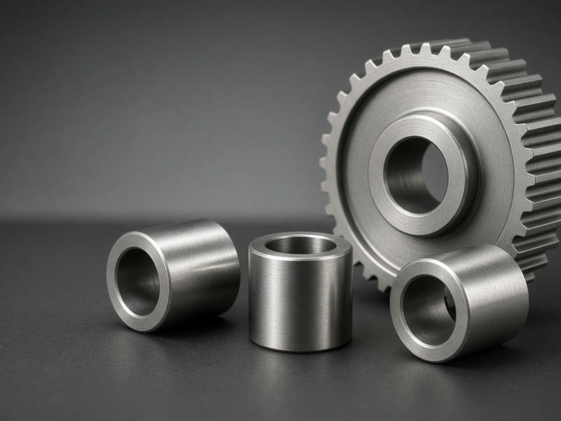
Custom CNC Machined Pulley Spacers
Precision tolerances for reliable power transmission systems, belt alignment, bearing support, and controlled axial positioning.
SpacerMFG manufactures pulley spacers to customer drawings and CAD models from our Shenzhen machining facility. We support automotive suppliers, robotics builders, industrial automation integrators, and heavy machinery OEMs.
±0.002
mm grinding tolerance
0.005
mm minimum runout
50,000+
production quantities
Alignment is performance
Why pulley spacer geometry dictates drive reliability
A spacer is not simply a dimensional filler. It establishes the structural datum that controls torque, tension, clamping forces, and bearing load distribution.
Parallel faces
Face parallelism and perpendicularity prevent shaft-bolt preload from tilting the pulley and causing angular runout.
Concentric rotation
Bore-to-OD concentricity limits rotating imbalance, high-frequency vibration, and shaft seal wear at elevated RPM.
Stable contact
Correct flatness, contact area, and surface finish help prevent local yielding, fretting corrosion, and lost bolt tension.
SHAFT SHOULDER     SPACER FACE A       PULLEY HUB       SPACER FACE B
      |                   |                  |                  |
  +---------+       +-----------+      +------------+      +---------+
  |  SHAFT  |=======|   BORE    |======|    BORE    |======|RETAINER |
  +---------+       +-----------+      +------------+      +---------+
                       <----------->
                       Parallel faces
                    Zero angular runout
Manufacturing capability
SpacerMFG CNC turning and milling
Multi-axis CNC lathes, live-tool turning centers, and precision surface and cylindrical grinding support cylindrical collars, stepped alignment bushings, and complex flanged pulley spacers.
| Machining parameter | In-house capability | Typical pulley spacer specification |
|---|---|---|
| Machining processes | CNC turning, turn-milling, surface grinding, cylindrical grinding | Single-setup turned parts |
| Outer diameter | Ø3.0 mm to Ø300 mm | Ø15 mm to Ø120 mm |
| Bore diameter | Down to Ø1.5 mm | Ø5 mm to Ø80 mm |
| Length / thickness | 1.0 mm to 450 mm | 3.0 mm to 75 mm |
| Standard dimensional tolerance | ±0.01 mm (±0.0004") | ±0.02 mm to ±0.05 mm |
| Precision grinding tolerance | Down to ±0.002 mm (±0.0001") | Critical face-to-face parallelism |
| Concentricity / runout | Within 0.005 mm to 0.015 mm | To match shaft fit class |
| Surface roughness | Ra 0.4 µm to Ra 1.6 µm | Ra 0.8 µm on locating faces |
| Batch volume | 1 to 50 prototypes; 100 to 50,000+ production | Scheduled repeat production |
Stepped spacers
Dual-diameter bodies for bearing inner-race location and seal clearance.
Flanged spacers
Integrated shoulders for belt guidance or broad frame contact.
Grooved designs
O-ring, labyrinth seal, and snap-ring relief features.
Keyways and slots
Milled drive features for synchronized shaft rotation.
Threaded features
Internal or external threads and clearance counterbores.
Material engineering
Select the alloy for your operating environment
Weight, tensile strength, corrosion resistance, wear, and thermal stability all influence the correct pulley spacer material. We machine standard metal grades to your drawing specifications.
Low inertia
6061-T6 and 7075-T6 aluminum for automation, robotics, and high-speed drives.
High load and wear
303/304/316L stainless steel, 1045 carbon steel, 4140 alloy steel, and brass for demanding interfaces.
| Material grade | Strength / density | Corrosion resistance | Best used for |
|---|---|---|---|
| Aluminum 6061-T6 | ~310 MPa; 2.70 g/cm³ | Good; excellent when anodized | General automation and low-to-medium load drives |
| Aluminum 7075-T6 | ~570 MPa; 2.81 g/cm³ | Moderate; anodizing recommended | High-speed robotics and automotive accessory drives |
| Stainless 304 / 303 | ~500–620 MPa; 7.93 g/cm³ | Excellent | Food processing, washdown, and medical drives |
| Stainless 316L | ~580 MPa; 8.00 g/cm³ | Superior in chemical and salt exposure | Marine and chemical handling equipment |
| Carbon steel 1045 | ~570–650 MPa; 7.85 g/cm³ | Low; plating or black oxide required | Heavy-load and cost-sensitive production |
| Alloy steel 4140 | ~850–1000+ MPa; 7.85 g/cm³ | Low; surface treatment required | High clamping torque and shock-loaded shafts |
| Brass C36000 / H59 | ~340–450 MPa; 8.50 g/cm³ | Good | Anti-sparking and low-friction interfaces |
Finishing and applications
Configured for your drive system
From lightweight servo mounts to corrosion-exposed agitator drives, each spacer configuration and finish is selected around the actual operating conditions.
Timing belt and serpentine idlers
Requirement: zero face runout to prevent rib wear.
Solution: stepped aluminum or hardened steel spacers ground flat within 0.005 mm, stopping against the bearing inner race without contacting the rotating outer ring.
Robotics and actuator mounts
Requirement: minimum rotational inertia and compact footprint.
Solution: thin-wall 7075-T6 aluminum with chamfered lead-ins, relief pockets, and clear or black Type II anodizing.
Conveyor and transmission shafts
Requirement: high axial load resistance under 10.9 or 12.9 bolt torque.
Solution: heat-treated 4140 spacers with ground end faces and black oxide or zinc-nickel finish.
Marine and chemical agitator drives
Requirement: resistance to salt water, washdown chemicals, and humidity.
Solution: passivated 316 stainless steel with Ra 0.4 µm ground contact faces to reduce crevice corrosion.
Available surface treatments and post-processing
Anodizing: Type II clear/color and Type III hardcoat for aluminum wear protection.
Electroless nickel: Uniform corrosion and wear resistance inside narrow bores and blind holes.
Black oxide: Cost-effective protection for steel parts in enclosed equipment.
Zinc / zinc-nickel: Sacrificial protection for outdoor and automotive drive systems.
Passivation: Removal of free iron to enhance stainless steel's passive layer.
Laser marking: Permanent part numbers, batch codes, and alignment marks.
Quality assurance
Measured against your drawing and GD&T
Every production batch follows an inspection plan based on your specifications, critical dimensions, material requirements, and geometric tolerances.
Raw material verification
Mill certificates, material XRF, and hardness testing.
In-process inspection
First-article checks, critical OD and ID dimensions, and thread gauge Go/No-Go checks.
Final inspection
CMM or optical inspection, surface roughness measurement, and plating thickness verification.
Metrology equipment and documentation
- Coordinate measuring machine: complex 3D features, true position, and geometric alignment.
- Optical comparators and vision systems: non-contact inspection of profiles, chamfers, radii, and micro-steps.
- Bore micrometers and air gauging: micron-level inner bore verification.
- Surface roughness testers: sealing face and bearing shoulder Ra measurement.
Reports available upon request
Full Dimensional Inspection Reports, Material Test Reports / Mill Certificates, and Surface Treatment Certificates.
Start your pulley spacer RFQ
Send your drawing and receive a clear path to production
Whether you need a dozen prototype stepped spacers or tens of thousands of serial-production units, SpacerMFG builds parts exactly to your drawing.
RFQ process
- Step 1: Send 2D prints in PDF, DWG, or DXF and 3D files in STEP or IGES.
- Step 2: Specify material grade, finish, tolerances, and quantity.
- Step 3: Receive a DFM review and formal quotation within 24 hours.
Talk with our engineering team
Submit your requirements through the contact channel below. Our team reviews CAD geometry for manufacturability, tooling paths, cost-efficient setups, and delivery quality.
- Email:
- info@spacermfg.com
- Machining facility:
- Supported files:
- STEP, STP, IGES, IGS, X_T, DWG, DXF, PDF